


 |
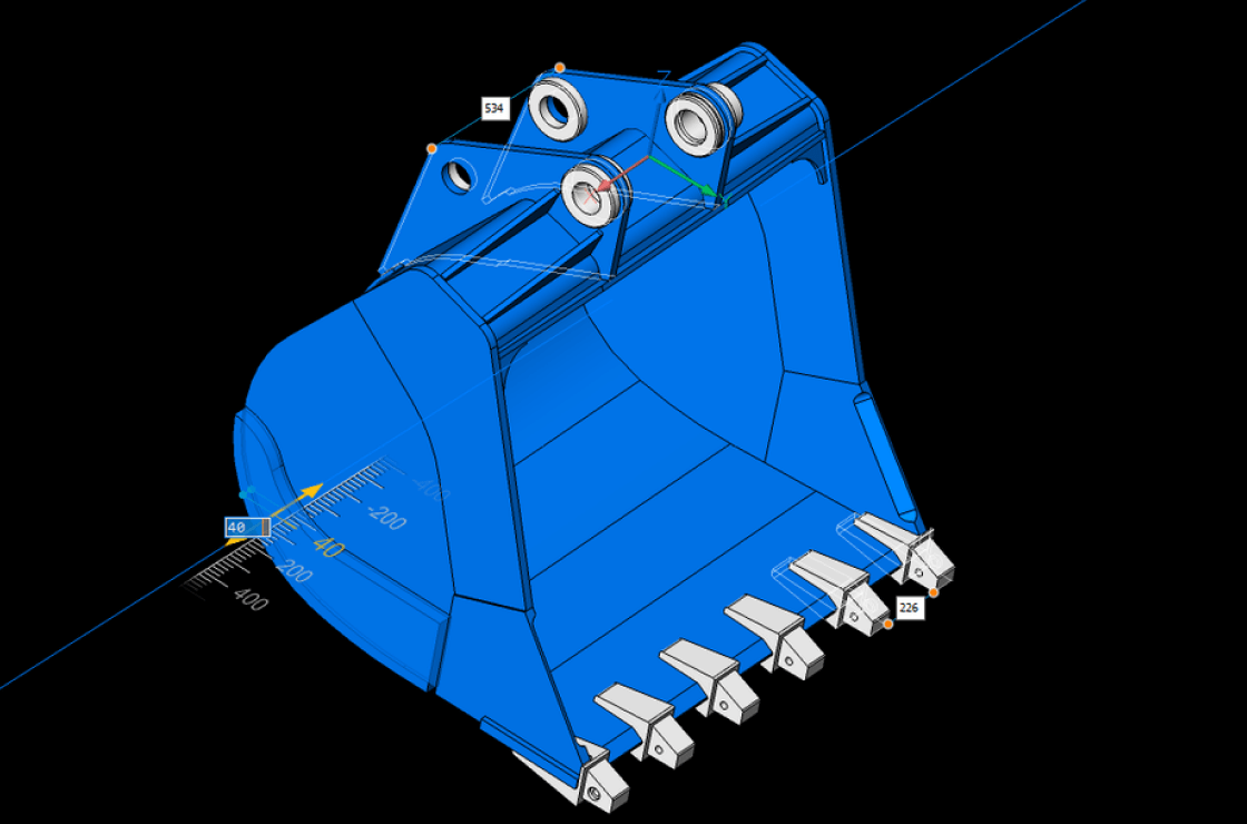
Design Parts and Components With BricsCAD Mechanical, the design process is simple. Start your design with a 2D sketch, then extrude, revolve, or sweep it to create a 3D solid. You can also use built-in 3D primitives to specify the initial shape of your part. Move on to the details using extrusions, fillets, chamfers, Boolean operations and edit using dynamic direct modeling. You control as much or as little of the form as you like with parameters. You can also import 3D solids and edit them as native components. |
 |
 |
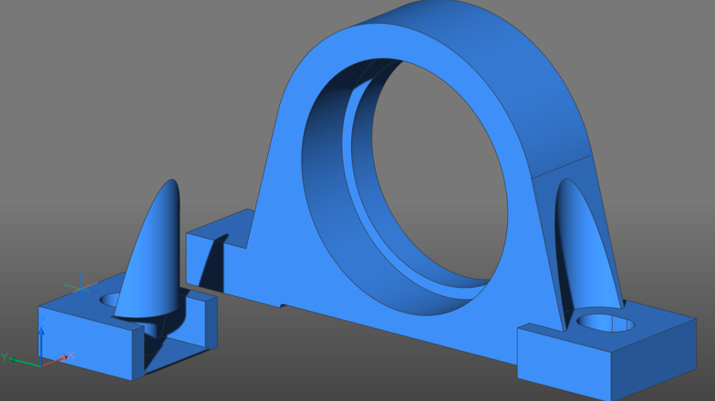 |
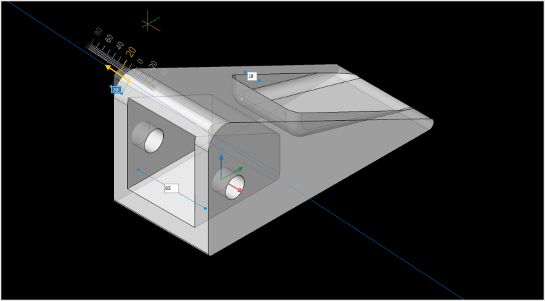
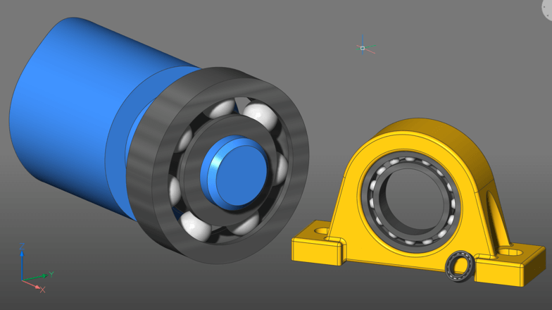
| Flexible 3D Modeling | 3D Parametrize and Constraints | Copy Features |
| Our unique 3D design approach combines dynamic and interactive direct modeling with the ability to add parameters only where needed and without the complexity of a history-based approach. | The PARAMETRIZE AI workflow turns parts into smart, parameter-driven components in seconds. Build constraint systems, drive parts formulaically, build table-driven components and change component parameters in the BricsCAD Properties Panel. | Model features once and use them many times with powerful tools that copy existing features in 3D solids such as holes, ribs and pockets. |
 |
 |
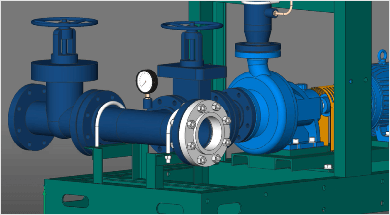 |
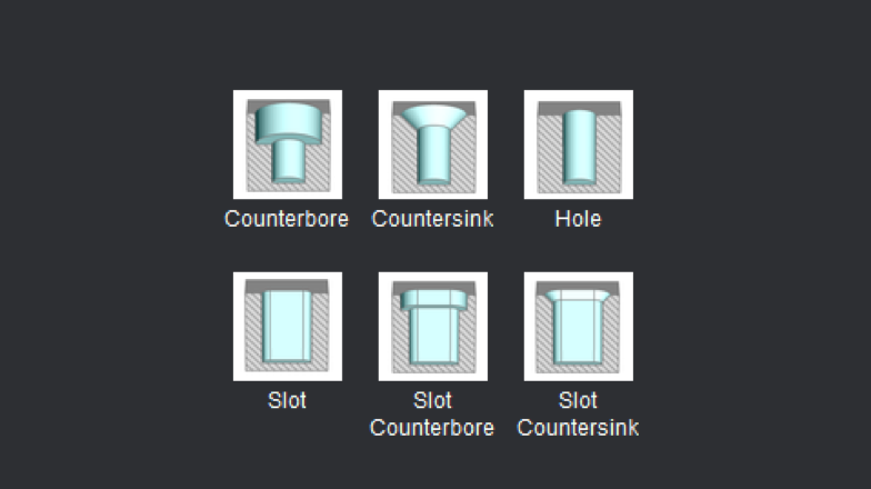
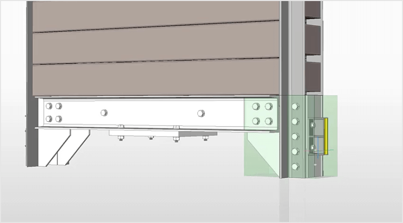
| Hole Feature Library | Automatically Align Copied Entities | Smart Piping Design |
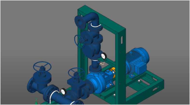
| BricsCAD contains a library of standard hole features – you can easily insert holes into your parts via drag and drop actions. | 3D COPYGUIDED automatically aligns copied sets of features to relevant geometry using automatically generated guide curves. You can explicitly select entities to use as guide curves or let BricsCAD determine them based on the drawing elements in your selection. | Create rigid pipework, then add parametric valves, flanges and associated fastenings. All from a comprehensive library of items, which intelligently resize correctly via a one-click process. |
| Create sheet metal part designs that are resilient and deeply editable | |
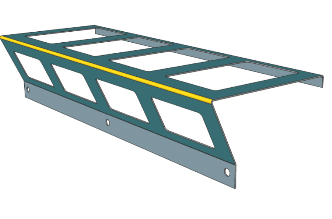 |
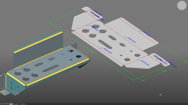
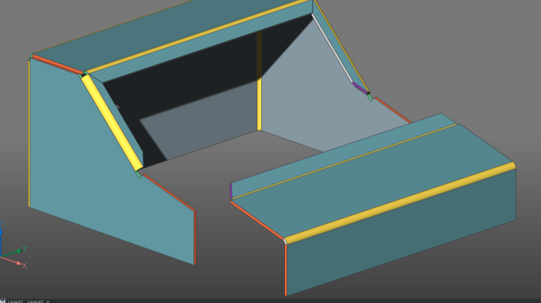
Import or Create From Scratch BricsCAD Mechanical can create sheet metal components from scratch and allows users to automatically convert solid parts to sheet metal with just one click. This robust approach lets you spend more time evolving your design and less time worrying about redefining sheet metal features. Rework at Any Time Sheet metal parts can be edited with the full power and freedom of direct modeling, while the consistency of each feature (flanges, bends, reliefs, junctions) is automatically maintained. Automatically Unfold Create un-folded 2D representations that are bi-directionally associated to the 3D sheet metal part. You can also use the unfolding engine to send parts to industry-standard CAM systems. |
 |
 |
 |
| Feature-based Direct Modeling | Convert-to-sheet-metal-parts | Unfolding |
| The flexibility of direct modeling maintains design intent, expressed as sheet metal features – flanges, bends, reliefs and others. | 3D models created in BricsCAD or other CAD systems can be converted to sheet metal automatically, with one click. Features can then be manually refined or changed to quickly achieve your desired form. | Create 2D and 3D unfolded representations to drive CAM systems. The 3D unfolded representation can be edited simultaneously to fix detected conflicts, while keeping the 3D folded part in sync. |
 |
 |
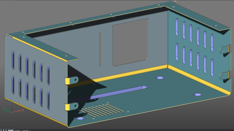 |
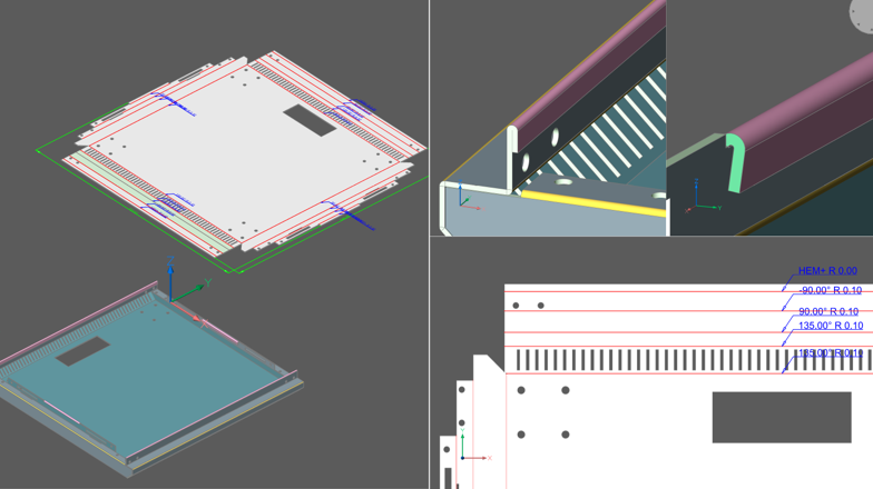
| Parametric Sheet Metal Parts | Hems | Form Features |
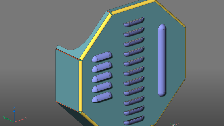
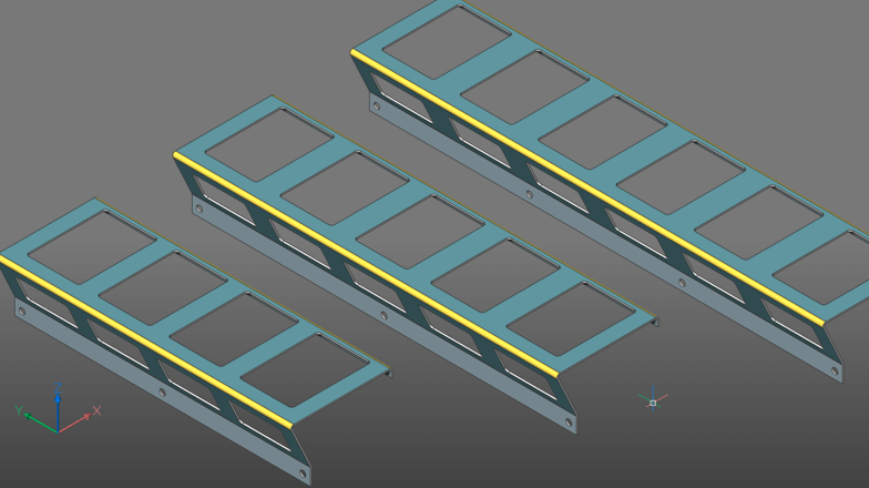
| Use the full power of 3D constraints, arrays and automatic parametrization to create different design variants from your sheet metal models. | The hem feature for Sheet Metal allows you to model a hemming metal-working process. BricsCAD supports open hems, teardrops and rounds with user-adjustable parameters. | BricsCAD Mechanical provides a library of parametric form features – such as louvers, bridges, embosses and others. You can also create complex ribs defined by any curve. |
 |
 |
 |
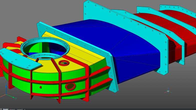
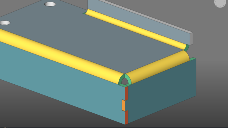
| Lofted Bends | Flanges, Bends, Junctions and Tabs | Reliefs and Splits |
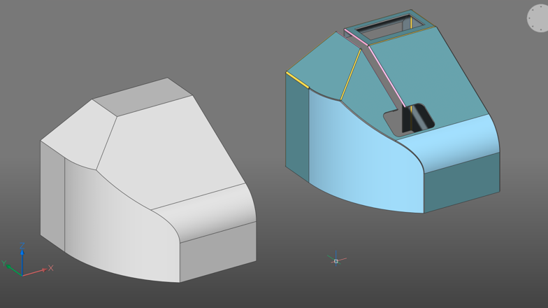
| You can create lofted sheet metal parts between two arbitrary 3D curves. BricsCAD Mechanical can recognize lofted bends in imported geometry and automatically decompose them into multiple flanges. | Create flanges in multiple ways: using a base flange, an edge flange or a via a contour tool. You can always change the way adjacent flanges connect – via a bend, a junction, or a tab-and-slot connection – to improve manufacturability. | Avoid material conflicts during the bending process by leveraging the library of reliefs in BricsCAD Mechanical. Split parts in a single click and automatically propagate the split to other corners in your model. |
| Build potentially complex assemblies and subassemblies using components designed in-house or by others. | |
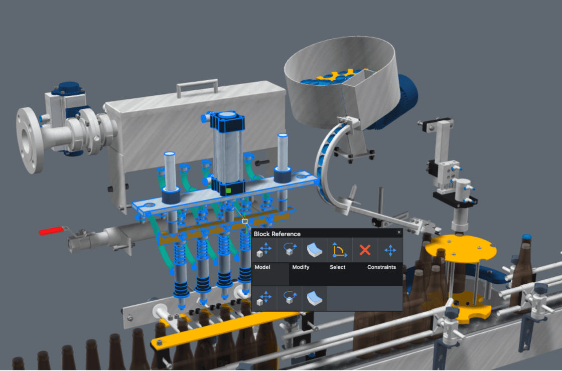 |
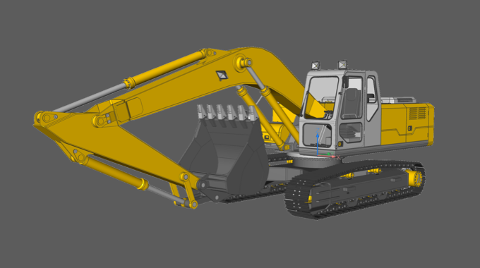
Bottom-up and Top-down Assembly Design BricsCAD Mechanical users can create complex hierarchies of parts and sub-assemblies using bottom-up or top-down design methods. You can import assemblies from different CAD systems using Communicator for BricsCAD, including Parametric geometry defined in those assemblies. |
 |
 |
 |
| BricsCAD offers the best and most familiar workflow for turning your mechanical designs into production drawings | |
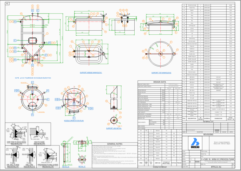 |
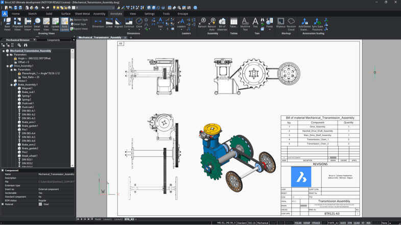
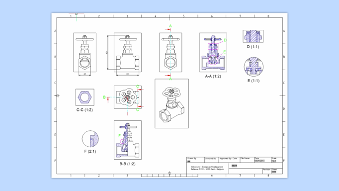
Drawing Views Automatically create drawing views of your 3D parts and assemblies and detail views easily with dimensions and annotations. If your 3D model changes, generated drawing views are updated automatically.
|
 |
 |
 |
| Fast Generation of Draft-quality Drawings | Automated Drawing Generation | Section Views |
| Speed up drawing layout using fast, draft-quality views and use multi-core CPUs to create detailed views in record time. BricsCAD Mechanical is responsive to your inputs during background drawing generation. |
Automatic drawing update Drawing views remain associated with the 3D model. Change a single part, subassembly, or the whole assembly and all 2D drawing views are automatically updated, allowing fast design iterations and changes. |
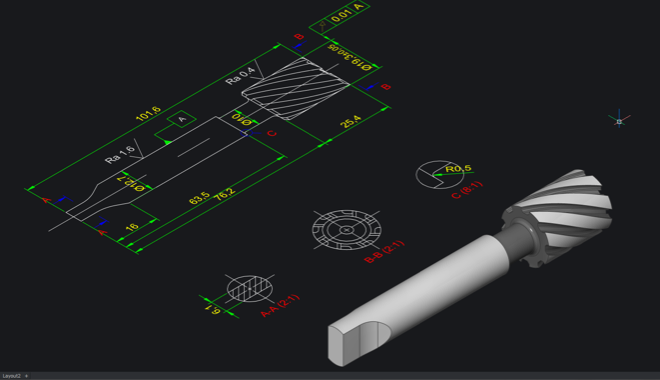
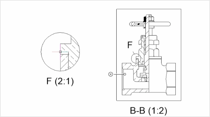
You can create section views of 3D parts and assemblies. Section planes can be defined by a line drawn on a base view, or you can create more complex sections: half sections, offset sections and aligned section views. |
 |
 |
 |
| Detail Views | Bill of Materials Table | Balloons |
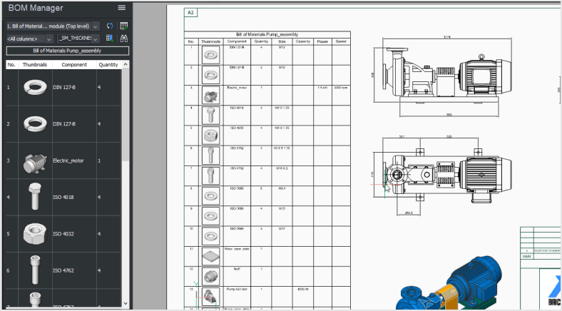
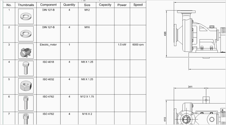
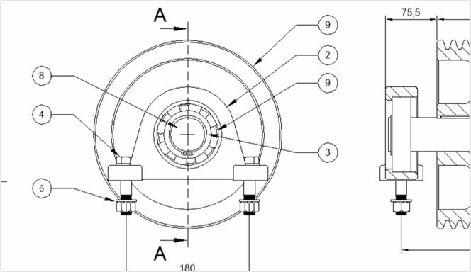
| BricsCAD Mechanical allows you to automatically create detail views from any existing view in your drawing layout. | The BOM panel lets you manage multiple BOM tables in your drawings. You can format each column individually, set up equations, sort tables and more. | BricsCAD Mechanical creates associative balloons for each component in an assembly and manages the display of those tags in all automatically generated 2D views. |
 |
 |
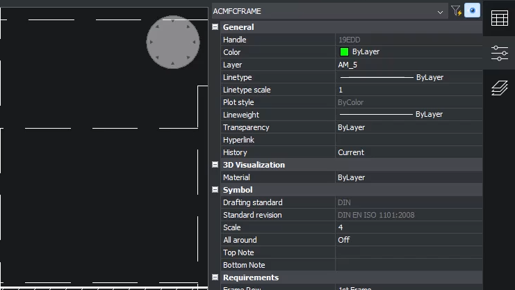 |
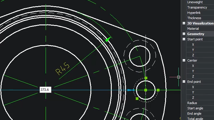
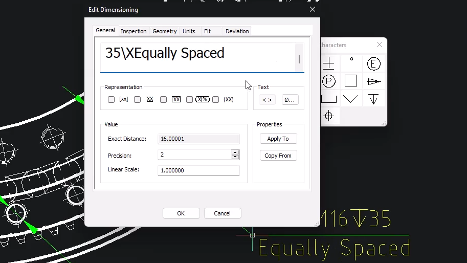
| Mechanical Symbols and Annotations | Power Dimensions | AutoCAD® Mechanical Compatibility |
| All the 2D detailing annotations you need, from datums and geometric tolerances to surface finishes to weld symbols and representations, are available at your fingertips to quickly create 2D production drawings. | The POWERDIM tool intelligently creates the right dimension for the selected geometry, including fits and tolerances, making dimensioning your drawing views effortless. | Easily open, edit and reuse symbols and annotations in your drawings created in AutoCAD Mechanical. |
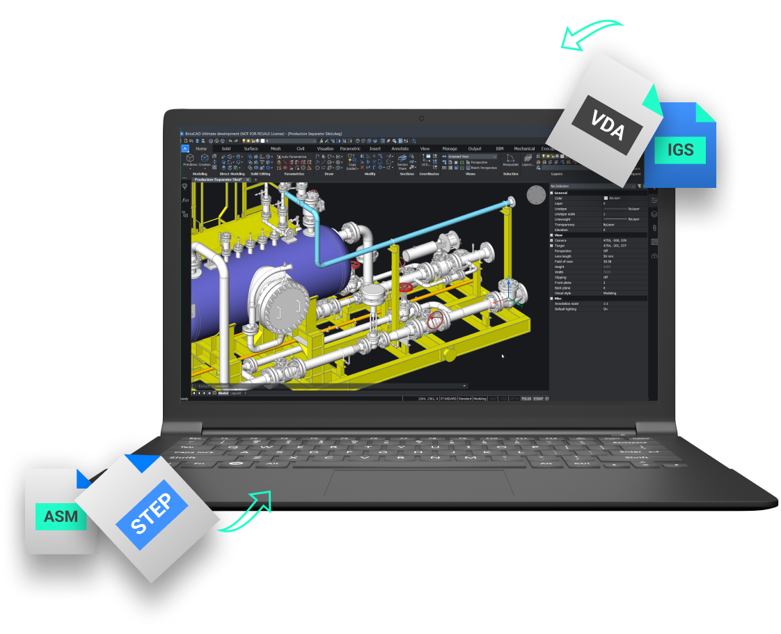 |
Multi-CAD Connectivity Bring CAD data from many other formats seamlessly into BricsCAD with Communicator for BricsCAD. Easily and quickly build it into your assemblies, modify it via direct modeling, or make it intelligent by applying parameters. |